2.11.9 dfilter(Pro)
Contents
Menu Information
Analysis : Signal Processing : IIR Filter
Brief Information
Create and apply an IIR filter
Additional Information
Minimum Origin Version Required: Origin 9.0 SR0
This feature is for OriginPro only.
Command Line Usage
dfilter method:=cheby1 order:=5 sample:=1000 wn:=50 filtfilt:=1 coef:=[<input>]<new>;
X-Function Execution Options
Please refer to the page for additional option switches when accessing the x-function from script
Variables
| Display Name |
Variable Name |
I/O and Type |
Default Value |
Description |
|---|---|---|---|---|
| Input Signal | iy |
Input XYRange |
|
Specify the input signal. |
| Response Type | type |
Input int |
|
Specify the response type of filter.
Option list:
|
| Method | method |
Input int |
|
Specify the filter design method.
Option list:
|
| Filter Order | order |
Input double |
|
Specify the filter order. |
| Unit | unit |
Input int |
|
Specify the unit for the frequency settings.
Option list:
|
| Sample Frequency (Fs) | sample |
Input double |
|
Specify the sampling frequency, available when the Unit is Hz. |
| Cutoff Frequency (Fc) | wn |
Input double |
|
When Filter Order is specified (not minimum), this variable is used to specify the cutoff frequency for the low pass and high pass. |
| Cutoff Frequency 1 (Fc1) | wn1 |
Input double |
|
When Filter Order is specified (not minimum), this variable is used to specify the first cutoff frequency for the band pass and band stop. |
| Cutoff Frequency 2 (Fc2) | wn2 |
Input double |
|
When Filter Order is specified (not minimum), this variable is used to specify the second cutoff frequency for the band pass and band stop. |
| Pass Frequency | wp |
Input double |
|
When Filter Order is minimum, this variable is used to specify the pass frequency for the low pass and high pass. |
| Stop Frequency | ws |
Input double |
|
When Filter Order is minimum, this variable is used to specify the stop frequency for the low pass and high pass. |
| Pass Frequency 1 | wp1 |
Input double |
|
When Filter Order is minimum, this variable is used to specify the first pass frequency for the band pass and band stop. |
| Stop Frequency 1 | ws1 |
Input double |
|
When Filter Order is minimum, this variable is used to specify the first stop frequency for the band pass and band stop. |
| Pass Frequency 2 | wp2 |
Input double |
|
When Filter Order is minimum, this variable is used to specify the second pass frequency for the band pass and band stop. |
| Stop Frequency 2 | ws2 |
Input double |
|
When Filter Order is minimum, this variable is used to specify the second stop frequency for the band pass and band stop. |
| Passband Ripple | rp |
Input double |
|
Specify the pass band ripples in dB. |
| Stopband Attenuation | rs |
Input double |
|
Specify the stop band attenuation in dB. |
| Forward-Backward Filtering | filtfilt |
Input int |
|
Specify whether to perform both forward and backward filtering on the input signal. |
| SOS Matrix | sos |
Output ReportData |
|
Output the designed IIR filter as the second order section (SOS) parameters form. |
| Zeros Poles and Gain | zpk |
Output ReportData |
|
Output the designed IIR filter as the zero-pole-gain form. |
| State-Space Form | abcd |
Output ReportData |
|
Output the designed IIR filter as the state-space form. |
| Coefficients | coef |
Output ReportData |
|
Output the designed IIR filter as the numerator coefficients and the denominator coefficients. |
| Output Signal | oy |
Output XYRange |
|
The output signal after filtering by the designed IIR filter. |
Examples
This example will show how to perform high pass with Butterworth method.
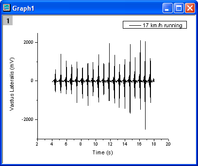
- Create a new project and import the data file <Origin Installation Directory>\Samples\Signal Processing\EMG Recording.dat.
- Highlight column B, and make a line plot by menu Plot: Line: Line.
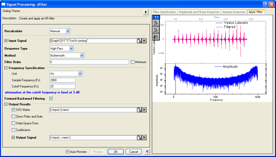
- Activate the graph, select menu Analysis: Signal Processing: IIR Filter to open the dialog, and then set the parameters as the following image shows.
- Response Type: High Pass
- Filter Order: 6
- Cutoff Frequency (Fc): 20
- Forward-Backwrad Filtering: checked
-
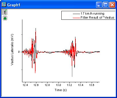
- Click the OK button, the result will plot together with the original signal. Zoom in the graph between about from 12.1 to 13.5. The result is shown in the following image.
-
More Information
For more information, please refer to our User Guide.
Related X-Functions
Keywords:infinite impulse response, signal, remove noise