18.3.2 Algorithms (IIR Filters)
IIR (Infinite Impulse Response) filter is a digital filter with feedback, as showing in the following picture.
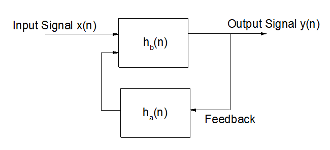
Digital filter is also often described in the difference equation form, which defines the relationship between output signal and input signal.
\[b_0*x(n)+b_1*x(n-1)+ \cdots +b_N*x(n-N)-a_0*y(n)-a_1*y(n-1)- \cdots -a_M*y(n-M) = 0 \]
then get
\[y(n) = \frac{1}{a_0} \left ( b_0*x(n)+b_1*x(n-1)+ \cdots +b_N*x(n-N)-a_1*y(n-1)-a_2*y(n-2)- \cdots -a_M*y(n-M) \right ) = \frac{1}{a_0} \left ( \sum_{i=0}^N b_i*x(n-i) - \sum_{j=1}^M a_j*y(n-j) \right )\]
where \(a_0 \ne 0\), N is the feedforward filter order, \(b_i\) is the feedforward filter coefficient, M is the feedback filter order, \(a_i\) is the feedback coefficient, x(n) is the input signal, and y(n) is the output signal. The term \(\sum_{j=1}^M a_j*y(n-j)\) is the feedback.
Digital Filter Representation
In Origin, there are four outputs for representation of IIR filter.
- Transfer Function
- Zero-Pole-Gain
- State-Space
- Second Order Section (SOS)
The transfer function of IIR filter is represented in the z-domain by the ratio of two polynomials of complex \(z^{-1}\). To find the transfer function of the IIR filter, rearrange the above equation as:
\[\sum_{i=0}^N b_i*x(n-i) = \sum_{j=0}^M a_j*y(n-j)\]
The z-transform is represented as:
\[X(z) = \sum_{}^{} x(n)z^n\]
Take the z-transform of each side of the filter equation, then get
\[\sum_{i=0}^N b_i*z^{-i}*X(z) = \sum_{j=0}^M a_j*z^{-j}*Y(z)\]
The transfer function of IIR filter in the z-domain represents:
\[H(z) = \frac{Y(z)}{X(z)} = \frac{\sum_{i=0}^N b_iz^{-i}}{\sum_{j=0}^M a_jz^{-j}}\]
As the transfer function shows above, the numerator is for the location of zeros, and the denominator for the poles. Then the transfer function can be rewritten as zero-pole-gain form.
\[H(z) = \frac{q(z)}{p(z)} = k*\frac{(z-q_1)(z-q_2) \cdots (z-q_N)}{(z-p_1)(z-p_2) \cdots (z-p_M)} = k* \frac{\prod_{i=1}^N (z-q_i)}{\prod_{j=1}^M (z-p_j)}\]
where k is the gain, \(q_i\) and \(p_j\) are the zeros and poles of the transfer function, respectively.
The state-space representation for the filter system can be defined as:
\[x(n+1) = Ax(n)+Bu(n)\]
\[y(n) = Cx(n)+Du(n)\]
where u(n) is the input, x(n) is the state vector, y(n) is the output, A is an m-by-m matrix, m is the filter order, B is a column vector, C is row vector, and D is a scalar.
The equivalent second order section representation of the digital filter transfer function is written as:
\[H(z) = g \prod_{k=1}^L H_k(z) = g \prod_{k=1}^L \frac{b_{0k}+b_{1k}*z^{-1}+b_{2k}*z^{-2}}{a_{0k}+a_{1k}*z^{-1}+a_{2k}*z^{-2}}\]
where g is the gain, \(b_{0k}, b_{1k}, b_{2k}\) are the numerator coefficients, and \(a_{0k}, a_{1k}, a_{2k}\) are the denominator coefficients. If the filter order m is even, \(L = m/2\), if m is odd, \(L = (m+1)/2\). And SOS can be represented as the following L-by-6 matrix.
\[SOS = \begin{bmatrix} b_{01} & b_{11} & b_{21} & a_{01} & a_{11} & a_{21} \\ b_{02} & b_{12} & b_{22} & a_{02} & a_{12} & a_{22} \\ b_{03} & b_{13} & b_{23} & a_{03} & a_{13} & a_{23} \\ \vdots & \vdots & \vdots & \vdots & \vdots & \vdots \\ b_{0L} & b_{1L} & b_{2L} & a_{0L} & a_{1L} & a_{2L} \\ \end{bmatrix} \]
How to Design IIR Filter
The typical procedure to design IIR filter is:
- Specify filter specification.
- Specify low pass analog filter prototype, and the available prototypes supported in Origin include Butterworth, Chebyshev Type I, Chebyshev Type II, and Elliptic.
- Frequency transform for analog filter
- Low pass to low pass, which transforms an analog low pass filter with cutoff frequency of 1 rad/s into a low pass filter with any specified cutoff frequency.
- \[H(s)= H(s')|_{s'=s/\omega_0}\]
- Low pass to high pass
- \[H(s) = H(s')|_{s'=\omega_0/s}\]
- Low pass to band pass
- \[H(s) = H(s')|_{s'= \frac{\omega_0}{B_{\omega}} \frac{(s/\omega_0)^2+1}{s/\omega_0}}\]
- Low pass to band stop
- \[H(s) = H(s')|_{s'= \frac{B_{\omega}}{\omega_0} \frac{s/\omega_0}{(s/\omega_0)^2+1}}\]
- Convert analog filter into a digital filter.
| Method | Squared Magnitude Response Function | Analog Filter Transfer Function |
|---|---|---|
| Butterworth | \[|H_a(j \Omega)|^2 = \frac{1}{1+ \Omega^{2N}}\] | \[H_a(s) = \frac{q(s)}{p(s)} = \frac{g}{(s-p_1)(s-p_2)\cdots (s-p_N)} = \frac{g}{\prod_{k=1}^N (s-p_k)}\] |
| Chebyshev Type I | \[|H_a(j \Omega)|^2 = \frac{1}{1+ \varepsilon^2 T_N^2(\Omega)}\] | \[H_a(s) = \frac{q(s)}{p(s)} = \frac{g}{(s-p_1)(s-p_2)\cdots (s-p_N)} = \frac{g}{\prod_{k=1}^N (s-p_k)}\] |
| Chebyshev Type II | \[|H_a(j \Omega)|^2 = \frac{1}{1+ (\varepsilon^2 T_N^2(\frac{1}{\Omega}))^{-1}} = \frac{\varepsilon^2 T_N^2(\frac{1}{\Omega})}{1+ \varepsilon^2 T_N^2(\frac{1}{\Omega})}\] | \[H_a(s) = \frac{q(s)}{p(s)} = g \frac{(s-q_1)(s-q_2)\cdots (s-q_N)}{(s-p_1)(s-p_2)\cdots (s-p_N)} = g \prod_{k=1}^N \frac{(s-q_k)}{(s-p_k)}\] |
| Elliptic | \[|H_a(j \Omega)|^2 = \frac{1}{1+ \varepsilon^2 U_N^2(\Omega)}\] | \[H_a(s) = \frac{q(s)}{p(s)} = g \frac{(s-q_1)(s-q_2)\cdots (s-q_N)}{(s-p_1)(s-p_2)\cdots (s-p_N)} = g \frac{\prod_{i=1}^N (s-q_i)}{\prod_{j=1}^N (s-p_j)}\] |
In the table above, \(\Omega\) is the frequency, N is the filter order, \(\varepsilon\) is the maximum oscillation in the passband frequency response, \(T_N\) is the Chebyshev polynomial, \(U_N\) is the Jacobian elliptic function, g is the scalar gain, s is the plane of Laplace transform, \(q_k\) or \(q_i\) is the zero, and \(p_k\) or \(p_j\) is the pole.
Transform the low pass filter into a high pass, band pass, or band stop filter with desired cutoff frequency. In Origin, the state-space form will be used in the frequency transform calculation. Assume the original transfer function of the low pass filter is \(H(s')\), and the transfer function after transform is \(H(s)\).
where \(\omega_0 = sqrt(\omega_1*\omega_2)\) is the center frequency, \(B_\omega = \omega_2 - \omega_1\) is the bandwidth, \(\omega_1\) and \(\omega_2\) are the lower and upper band edges respectively.
To convert analog filter into a digital filter, Origin uses the bilinear transformation, which is defined by expression:
\[s = \frac{1-z^{-1}}{1+z^{-1}}\]
Forward and Backward Filtering
Origin allows to perform the forward and backward filtering, which will result to zero-phase distortion. First of all, it will perform filtering the data in the forward direction, and then reverses the filtered data, then runs it back through the filter again.